Senior Design Project
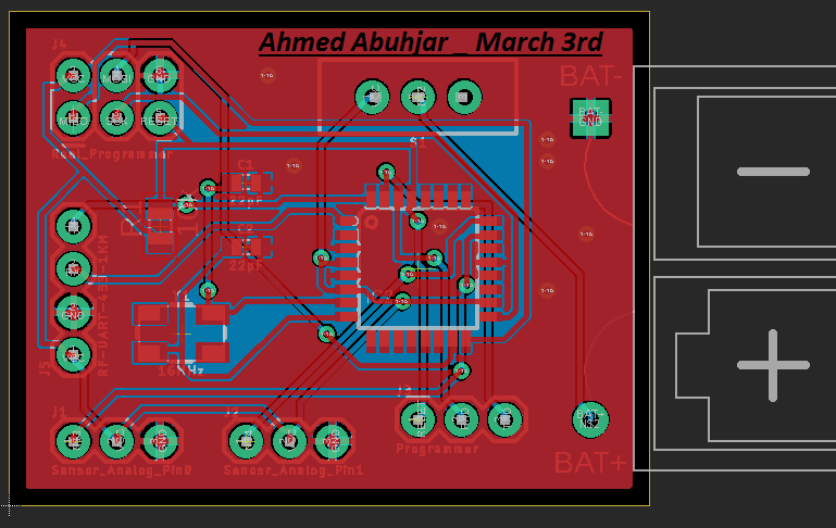
IoT environmental monitoring system is a network of sensors from which it will collect soil moisture readings and analyze the data to determine the possibility of dryness in the crops of user's farm. The purpose of this product is to make systems that monitor crops easier and smarter by providing customers and farmers with an automated system solution that will collect data which in turn will be relayed to a user website that helps providing remote access through an easy use. Thus, the farmers will then be able to determine if the crops need to be irrigated, which will not only maximize the agricultural production with minimum cost, but also will minimize the burden of farmers who could find themselves away from their farms for extended periods of time.
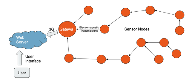
The system is primarily intended for farmers, but it will also be useful for anyone who wants to do environmental monitoring. It will be easy to configure our nodes to capture any type of data a client might want. Our users will generally have a low technical understanding which is something we will need to account for. The users can place the home node in a protected area then scatter the leaf nodes around the land they want to monitor. The leaf nodes will record and transmit data to the home node. The home node will upload the data to the website where the client will be able to see.
The system is primarily intended for farmers, but it will also be useful for anyone who wants to do environmental monitoring. It will be easy to configure our nodes to capture any type of data a client might want. Our users will generally have a low technical understanding which is something we will need to account for. The users can place the home node in a protected area then scatter the leaf nodes around the land they want to monitor. The leaf nodes will record and transmit data to the home node. The home node will upload the data to the website where the client will be able to see.
| Project_Plan.pdf |
| Design_Document.pdf |
| final_presentation_ee_491.pptx |
Projects
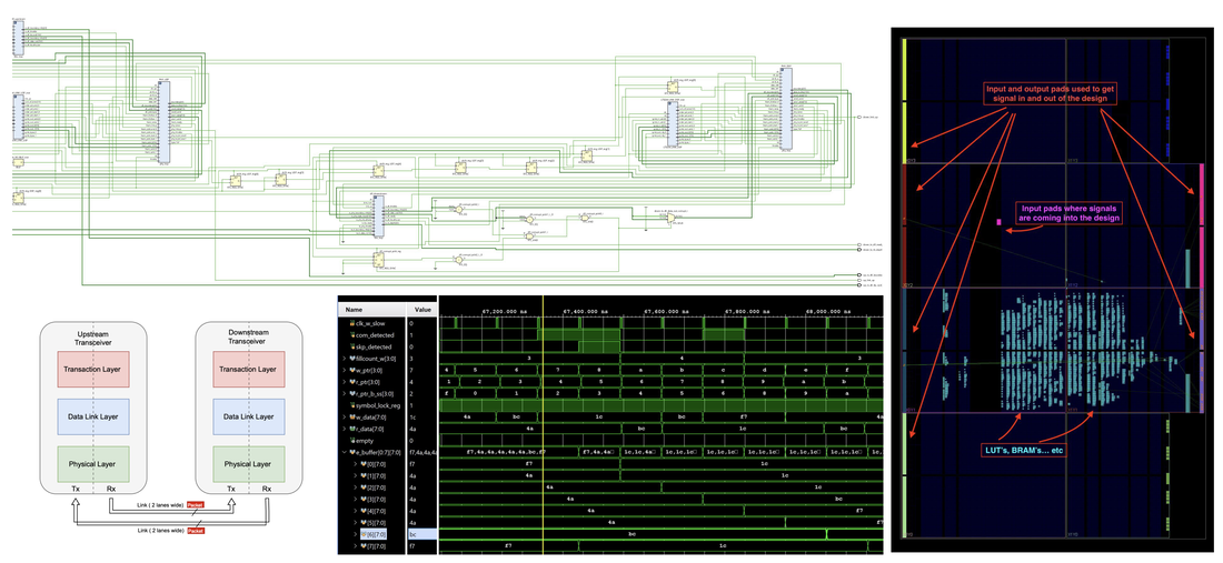
PCIe RTL Design, Simulation and FPGA PnR
| pcie_2024.pdf |
__________________________________________________________________________________________
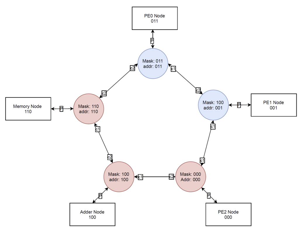
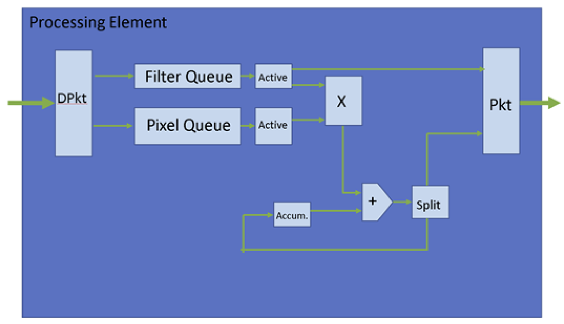
Convolutional Neural Network with Asynchronous Network on Chip:
| network_on_chip_convolutional_neural_network.pdf |
| cnn_with_async_noc_final_report.pdf |
__________________________________________________________________________________________
Dendritic Branch with Two Synapses:
| dendritic_branch_with_two_synapses.pdf |
__________________________________________________________________________________________
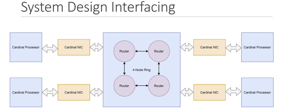
Network on Chip with 4-Node Multi-Core Processor:
| noc_with_chip_multiprocessor.pdf |
__________________________________________________________________________________________
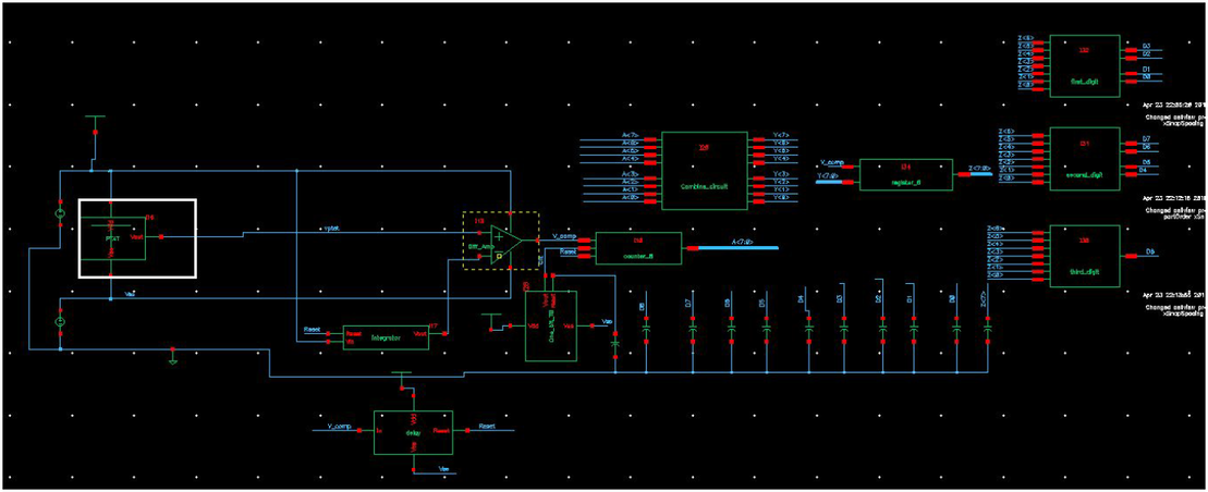
Temperature Sensor Using Diodes: This temperature sensor design employs temperature-dependent devices, specifically diodes. The circuit diagram depicting the entire configuration is presented below. The sensor will periodically assess the changing temperature and subsequently exhibit a decimal representation of the measurement in Celsius degrees. The sensor is designed to provide accurate measurements within the temperature range of -20°C to 100°C.
A Boolean signal is generated by the counter based on the voltage difference between two diodes in the PTAT. The counter continuously counts until a predetermined point determined by an integrator circuit. It was essential for the region on the voltage vs. time graph of the integrator to be nearly linear, though not necessarily perfect. This linearity is a crucial aspect of the design to maintain consistent proportionality between the PTAT output and the corresponding Boolean signal from the counter. Otherwise, assigning a Boolean number for each temperature measurement would have been exceedingly complex.
Furthermore, other logic circuits were incorporated into the design, including a combinational circuit that takes inputs from the counter to generate a temperature value in Boolean format. A register was utilized to store the measured values. Subsequently, the Boolean number stored in the register is fed into a BCD converter, which, in turn, drives a 7-segment display device (LF-3011A).
| temperature_sensor_using_diodes_.pdf |
__________________________________________________________________________________________
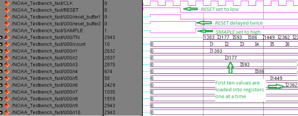
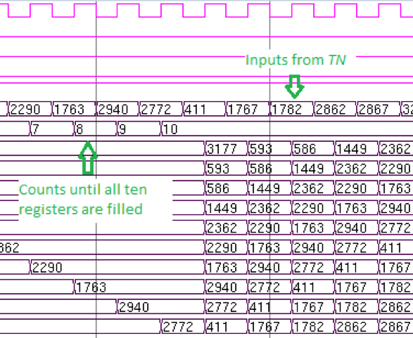
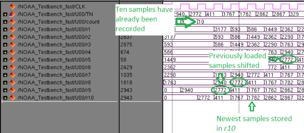
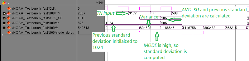
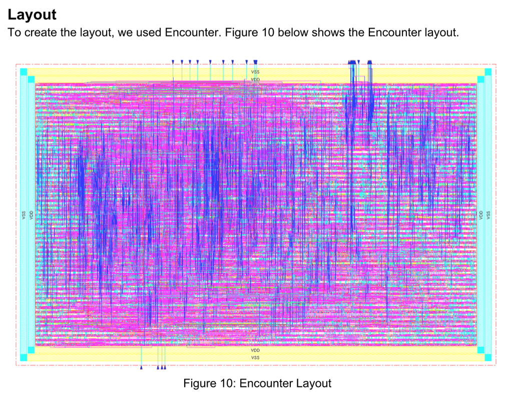
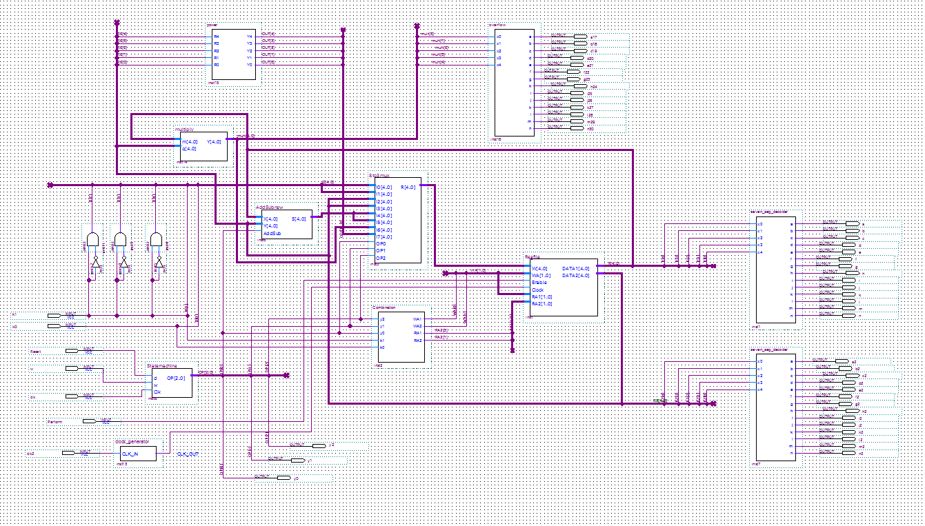
Digital VLSI Project:- Calculating the average and standard deviation for temperature readings: Our final project is to create a circuit that helps getting the average and the standard deviation for the samples that are relayed from the sensors in the IoT network. Specifically, we had to design a circuit that takes several samples of temperature inputs and then have the circuit do more than one arithmetic operations to determine the average and the standard deviation for the last ten samples. This project was done using Verilog coding in ModelSim software. Part of the Verilog code for the design is shown below. We first had to implement the code that satisfies the requirement using Verilog. The circuit will periodically take samples for temperature measurement. After the result has been confirmed to be satisfactory, we then synthesized the circuit using RTL method. After synthesizing the circuit, we optimized our design to make it small in size and more power efficient by reducing the number of clock cycles the system can operate with. This project was a group work, and we have cooperated to have the project meet all the requirements. We organized and implemented the code and synthesized and optimized the corresponding logic circuit.


| Digital_VLSI.pdf |
__________________________________________________________________________________________
Handheld Calculator: I designed a handheld calculator using Quartus Software. The calculator is primarily designed using logic gates, registers and ALUs, some of which were implemented using hard code in VHDL. The entire design consists of several parts. The finite state machine, the arithmetic unit, and the register file. Using the FPGA Cyclone board, I tested the design to verify that it outputs the correct result based on the operation chosen.
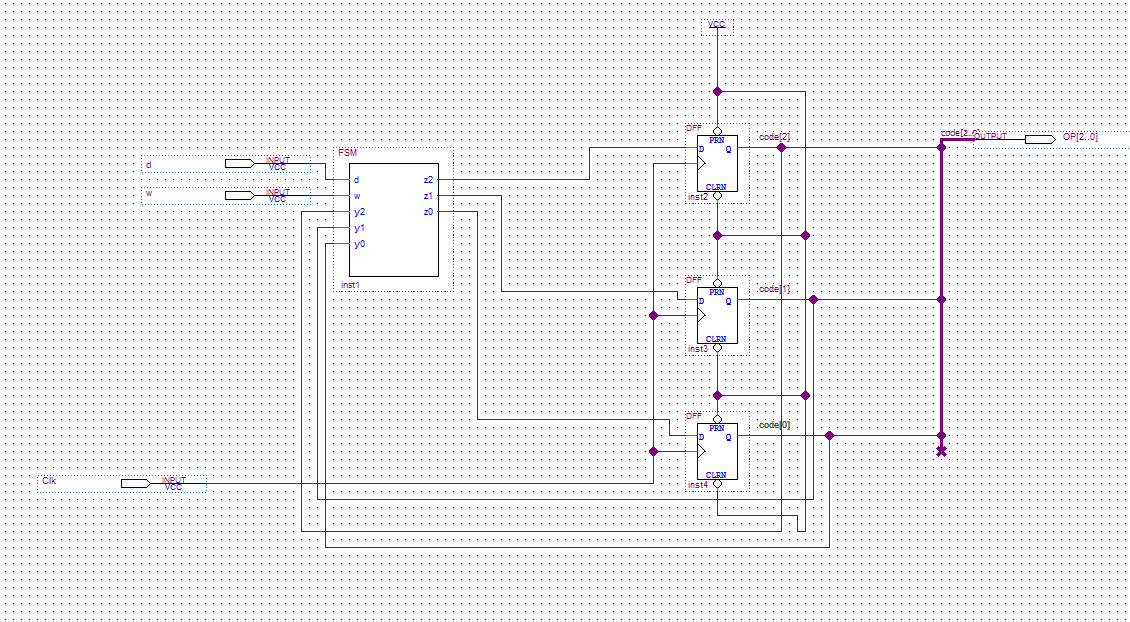

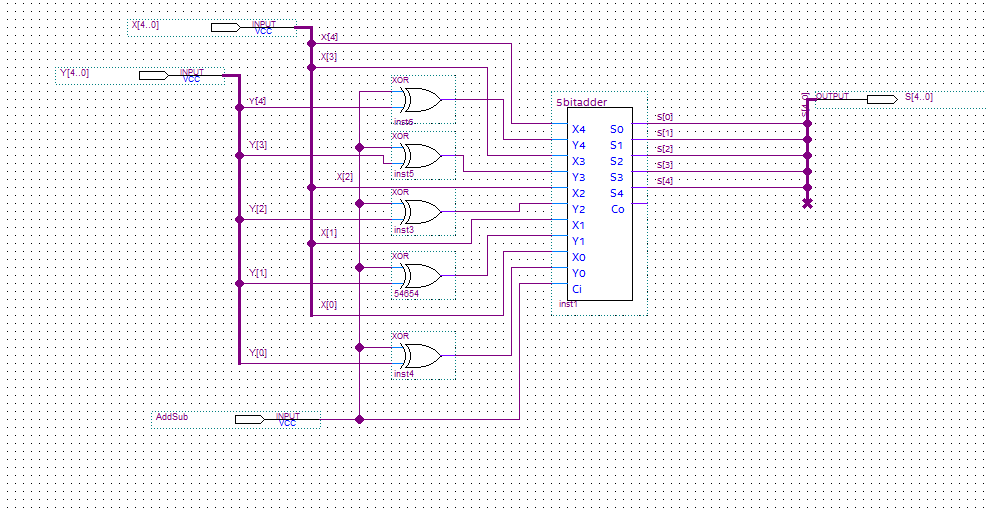
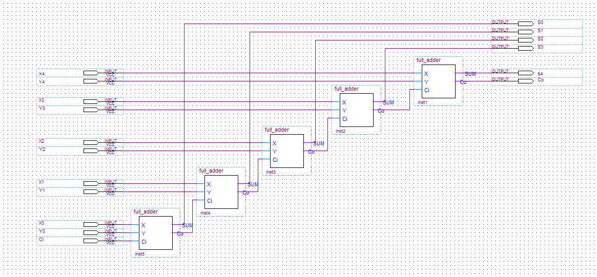
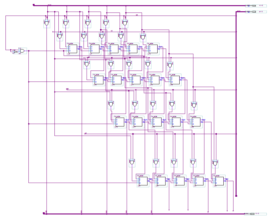

| Handheld_Calculator.pdf |
__________________________________________________________________________________________
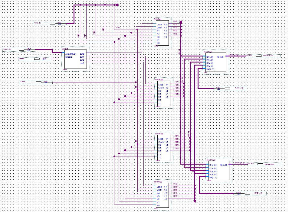
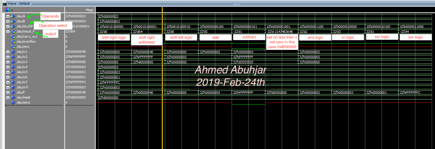
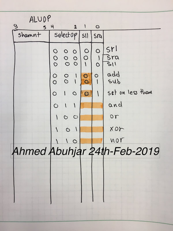
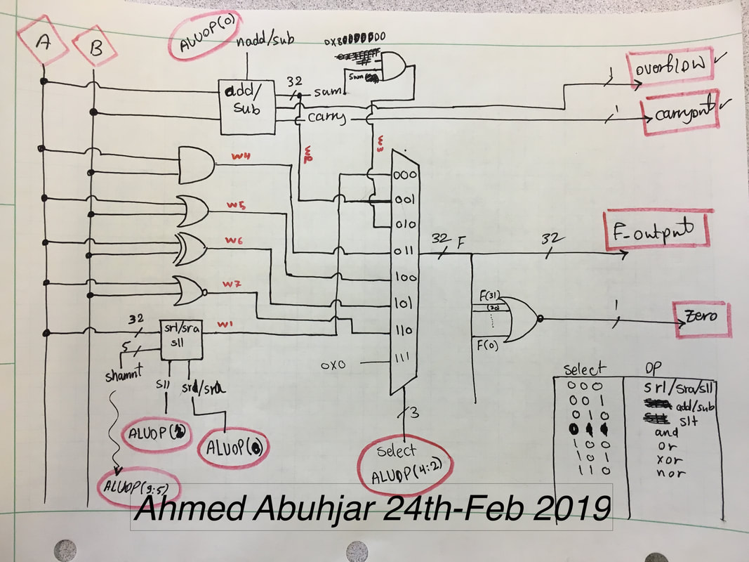
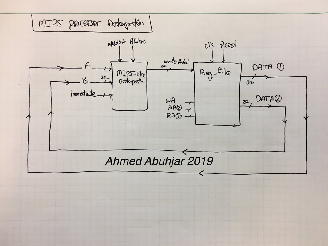
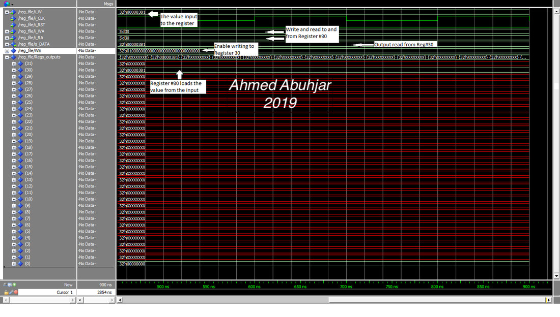
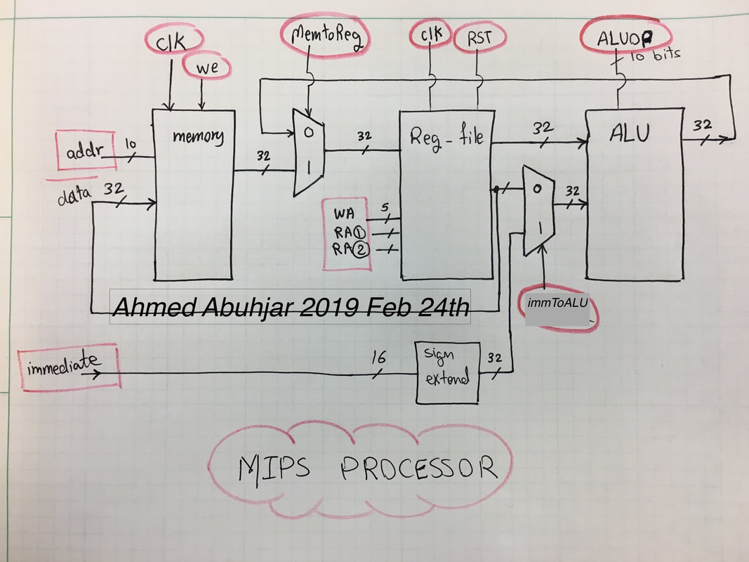
MIPS processor *(2019 24th-Feb): This project is to implement and design a 32-bit MIPS processor using ModelSim software and VHDL coding. My design implements several MIPS instructions including jump, jump and link, load and store, shift logic and shift arithmetic, computations, branching and more. To increase the instructions throughput of the system and to make the CPU much faster, I have modified the design using the pipelining technique. By the end of this project, I equipped myself with the ability to design more complex general purpose CPUs rather than small computational circuits.

__________________________________________________________________________________________
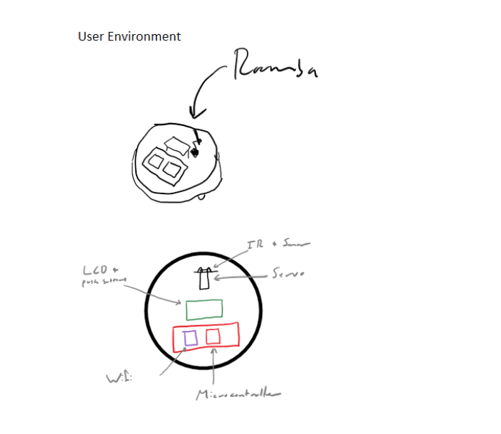
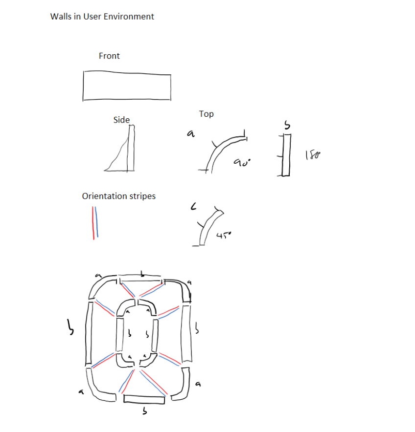
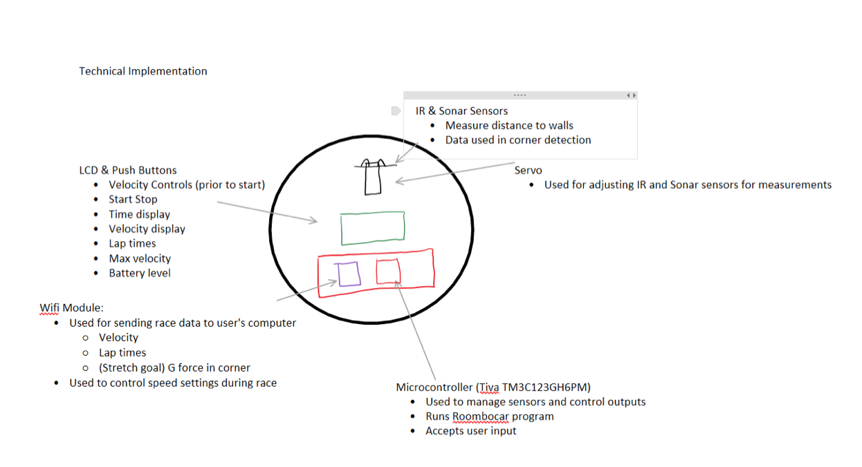
Roombocar: In this group project, we programmed a robot in a way so that it caters the needs of cars enthusiasts. Using C language in programming the robot, we were able to implement and make a mini self-driving fast car that can detect the edges and read the turns along the path of the course. Suitable for a wide variety of tracks and obstacles, the Roombocar will be able to scan and read the path and react accordingly. Using multiple Roombocars, the art of racing comes into play as the user can beef up and modify the Roombocar to try to gain the edge in the competition. This state of art technology is the future and will be the driving force in not only racing but also everyday cars.
__________________________________________________________________________________________
Optical signaling device: This device is optical signal device. It sent infrared signal from two oscillators set on specific frequencies. When the photodiodedetects a specific frequency, it will light up a red or green LED diode otherwise none of the LEDS will light up.
The circuit works as follows. In the IR transmitter circuit, I have two Wien bridge oscillators oscillating at different frequencies. One oscillate at around 1 and 2khz and the other around 10 and 20khz frequency. The output of each oscillator is connected to a push button. IR LED is connected to a collector of a BJT transistor. A 2.2k resistor is connected to the BJT and to the push button of the two oscillator. On the receiver part, I have two filters, one at low pass and the other at high pass. If we push on the low frequency button, the LED of the low pass turns on. Same for the high frequency. If any of the button was press, no LED lights up. On the high pass circuit, I put an amplifier to amplify the signal of the output.
The circuit works as follows. In the IR transmitter circuit, I have two Wien bridge oscillators oscillating at different frequencies. One oscillate at around 1 and 2khz and the other around 10 and 20khz frequency. The output of each oscillator is connected to a push button. IR LED is connected to a collector of a BJT transistor. A 2.2k resistor is connected to the BJT and to the push button of the two oscillator. On the receiver part, I have two filters, one at low pass and the other at high pass. If we push on the low frequency button, the LED of the low pass turns on. Same for the high frequency. If any of the button was press, no LED lights up. On the high pass circuit, I put an amplifier to amplify the signal of the output.